
www.ptreview.co.uk
15
'26
Written on Modified on
SEJFO transforms automation sales with Visual Components simulation
By replacing static CAD and PowerPoint with Visual Components simulation, SEJFO Group achieved clearer customer communication, safer robot selection, validated cycle times, and quotes that win deals.
www.visualcomponents.com
Application Area: Factory Automation Simulation, 3D Layout Validation, Technical Sales Engineering
Industry Sector: Manufacturing, Industrial Automation Systems
Swedish automation system supplier SEJFO Group has adopted Visual Components 3D simulation software to replace static CAD and PowerPoint workflows within its sales and engineering departments. The deployment establishes a unified digital thread linking conceptual factory automation layout design to shop-floor validation. By integrating this software-defined configuration tool, the company standardizes its distributed engineering communications, validates cycle times, and reduces project delivery risks across multi-axis automated lines.
Overcoming Conceptual Vagueness and Robot Kinematic Guesswork
Industrial system integrators face significant operational hurdles when communicating highly complex, parallel automation processes to non-technical stakeholders or distributed project teams. Prior to the implementation, SEJFO Group’s technical sales team relied on either deep, static CAD files that overwhelmed customers or high-level presentation slides that left mechanical operations open to interpretation. This conceptual variance resulted in misaligned expectations between clients and internal automation developers.
Operationally, the engineering workflow relied heavily on manual estimation when selecting industrial robots and configuring cycle times. Without dynamic toolpath and clearance validation during the initial quotation phase, the organization faced risks of geometric layout collisions, incorrect robot sizing, and unverified process times. To eliminate this operational ambiguity and mitigate financial risks stemming from post-sale design deviations, SEJFO Group selected a unified 3D simulation platform featuring an accessible eCatalog component library.
Implementing Collaborative Digital Twins from Proposal to Production
The integration of the 3D simulation environment optimizes the lifecycle of custom factory automation projects through a series of connected digital steps:
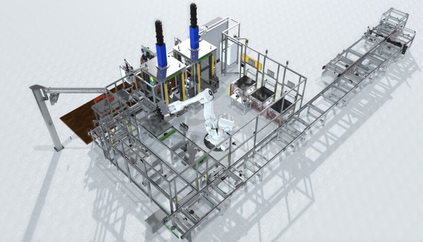
- Dynamic Layout and Parallel Process Visualization: Technical sales engineers use the simulation platform to author 3D moving concepts that explicitly demonstrate concurrent operations across multiple machine resources. This visibility allows both internal teams and prospective clients to audit complex timing sequences that are impossible to accurately represent in traditional spreadsheet or presentation formats.
- Kinematic Validation and Risk Mitigation: Rather than estimating machinery capabilities, concept developers test exact robot kinematic paths and validate layout footprints within the virtual space before submitting proposals. Potential clearance constraints or throughput bottlenecks are identified and modified during the iterative concept phase.
- Component Standardization: The platform's integrated eCatalog dictates early component selection. Standardized machinery assets utilized during the rendering of the initial sales concept carry directly into final engineering, which accelerates delivery cycles and ensures the built machine mirrors the quoted model.
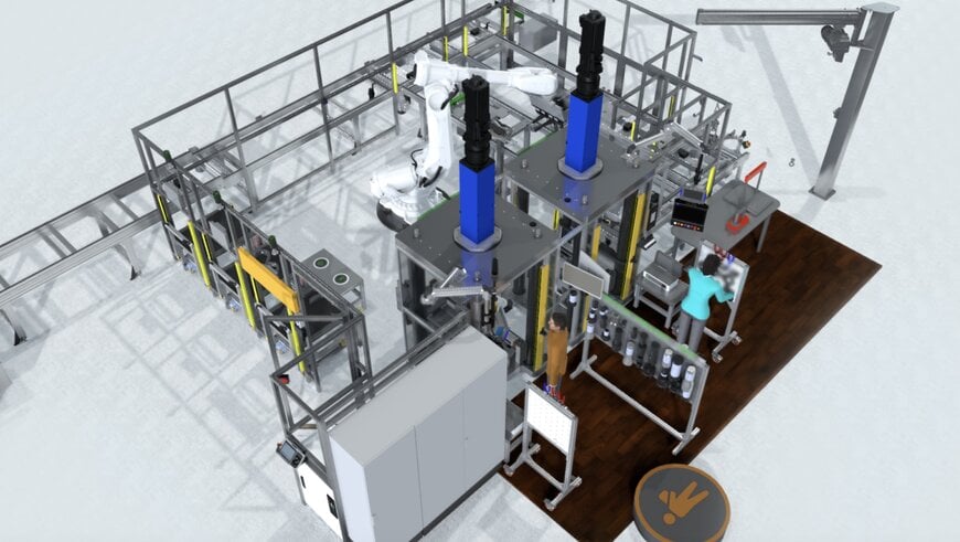
- Unified Cross-Department Engineering Thread: When a project is secured, the validated simulation serves as the geometric foundation for the development team. This continuity minimizes engineering deviations between the sold concept and final shop-floor execution, preventing unexpected integration costs. Furthermore, the model supports virtual reality (VR) configurations, allowing project managers to visually navigate and inspect the virtual assembly lines prior to equipment procurement.
Additional Context
The section below examines the technical specifications and operational benchmarks not included in the original application story.
Comparative Analysis of Simulation-Driven Engineering
Traditional automation engineering workflows rely on separate systems for mechanical drafting, spreadsheet-based cycle calculation, and manufacturer-specific robot emulation tools. Unifying these functions into a single discrete-event simulation toolpath alters the operational profile of the system integrator:
- Cycle Time Precision: Dynamic multi-axis kinematic simulation eliminates the standard 10% to 15% error margin typical of manual spreadsheet estimation by factoring in true acceleration profiles, deceleration curves, and joint-speed limitations of specific industrial robot models.
- Proposal Velocity: The utilization of modular eCatalog components allows engineering teams to execute rapid design iterations, converting long single-design phases into multiple rapid conceptual loops within a standard three-week quoting window.
- Error Reduction: Catching spatial clashes, joint limits, and singular points during the pre-sale phase decreases engineering change orders (ECOs) during physical floor installation, protecting project margins.
Technology Architecture Benchmarks
Based on the technology architecture benchmarks evaluated within the sector, transitioning from a disparate, manual configuration setup to an integrated 3D digital twin platform changes how operational data is handled:
Based on the technology architecture benchmarks evaluated within the sector, transitioning from a disparate, manual configuration setup to an integrated 3D digital twin platform changes how operational data is handled:
- Data Synchronization: Under a traditional static design workflow, modifications are heavily fragmented; any layout revisions executed within mechanical CAD tools must be manually cross-referenced across separate spreadsheets, text documentation, and cycle charts. Conversely, an integrated 3D simulation environment provides fully unified data processing, meaning any geometric or localized change made to the 3D model instantly calculates and updates operational timelines, robot kinematics, and downstream visual outputs in real time.
- Stakeholder Alignment: Traditional methods often suffer from low baseline alignment because abstract 2D engineering drawings or static block diagrams rely heavily on the technical background and subjective interpretation of the individual viewer. An integrated simulation environment remedies this by providing high alignment through uniform 3D animations and moving assets, establishing a single visual source of truth that is immediately accessible to both technical developers and non-technical business clients.
- Asset Reuse: The reuse of engineering data is highly inefficient in traditional setups, as proprietary or custom component models require distinct manual remodeling or tedious copy-pasting out of siloed, historical project directories. In contrast, a modern simulation platform enables continuous asset optimization where newly verified machinery designs and custom cells are saved directly back into a centralized digital twin library, systematically raising the baseline quality, speed, and fidelity of all future concepts.
Edited by Romila DSilva, Induportals Editor, with AI assistance.
